Quadruped Robot & Custom Web OS
DEC 2025| Personal Project
Overview
This project encompasses the entire lifecycle of a 12-DOF (Degree of Freedom) quadruped robot—from raw C++ embedded firmware handling complex trigonometric inverse kinematics to a modern, glassmorphic web dashboard that communicates over Web Serial API. It is designed to demonstrate advanced robotic mobility and intuitive telemetry monitoring.
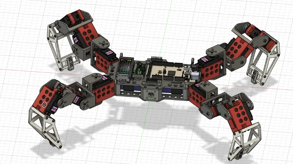
3D CAD Model
Embedded Firmware & Inverse Kinematics
The central controller manages a PCA9685 16-channel PWM driver via I2C at 50Hz. The custom C++ firmware executes a **3-DOF Inverse Kinematics (IK) Engine** capable of calculating exact servo angles for given XYZ foot distances. Hardware offset calibration and default neutral postures are persistently managed using EEPROM. The robot natively evaluates a dynamic **12-step creep gait engine**, orchestrating coordinated swing, push, and lift behaviors for perfectly balanced omnidirectional locomotion.
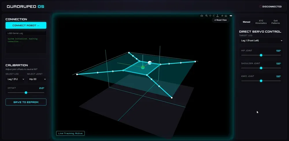
Quadruped OS Dashboard
To control and monitor the robot, I engineered **Quadruped OS**, a browser-based visualization dashboard using HTML, CSS, and Vanilla JS. It connects over the Web Serial API directly to the robot for ultra-low latency. Features include:
• **Real-Time 3D Viewer:** Renders the robot's physical posture live using Plotly.js.
• **Calibration Studio:** Visually adjust and commit EEPROM joint offsets.
• **Direct IK Control:** Target specific XYZ coordinates for individual legs without manually mapping degrees.
• **Omnidirectional Drive:** A built-in D-pad interface that live-streams gait vectors and speed parameters.
QuadrupedController.ino Anatomy
The central embedded firmware spans over 500 lines of robust C++ code managing everything from hardware pulses to high-level motion planning. Here is how it functions step-by-step:
**1. Hardware & Memory Initialization:** Bootstraps the PCA9685 driver via I2C and sets servo frequencies to 50Hz. Crucially, it reads the onboard EEPROM to load pre-calibrated joint offsets and the saved 'home' posture, applying them immediately so the robot stands up securely and perfectly aligned.
**2. Serial Command Interpreter:** Continuously listens to the UART serial port for incoming string commands. It decodes a custom protocol covering direct joint positioning (`L1S1:90`), IK mapping (`MOVE:1:50,0,-50`), EEPROM storage (`SAVE`), offset calibration (`CALIB:`), and autonomous gait execution (`WALK:F:5`).
**3. Smooth Interpolation Loop:** To prevent sudden mechanical jerks that can damage the motors or cause the robot to collapse, the firmware uses a non-blocking `millis()` loop running every 20ms (`updateServosSmoothly()`) to seamlessly transition the current physical angles towards the requested target angles.
**4. Inverse Kinematics Engine:** The geometric core of the robot. It takes a Cartesian XYZ request for a leg tip and mathematically works backwards using trigonometry constraints and the Law of Cosines to calculate the precise Hip, Shoulder, and Knee angles needed to reach that 3D coordinate.
**5. 12-Step Creep Gait Engine:** For omnidirectional walking, the program shifts into an automated finite state machine (`updateGait()`). By executing a highly coordinated sequence of *Lift, Swing, Plant, and Push* across diagonal leg pairs, the robot achieves static stability—walking forwards, backwards, or executing zero-radius yaw turns while always keeping three feet planted on the ground.
Kinematic Solution Engine
QuadrupedController.ino
1void calculateIK(int legIndex, float x, float y, float z) {
2  float L = sqrt(x * x + y * y);
3  float gamma = atan2(y, x);
4
5  float L1 = L - L_COXA;
6  if (L1 < 0) L1 = 0;
7  float D = sqrt(L1 * L1 + z * z);
8
9  // Prevent impossible stretching
10  if (D > (L_FEMUR + L_TIBIA)) {
11    D = L_FEMUR + L_TIBIA - 0.01;
12  }
13
14  float alpha1 = atan2(abs(z), L1);
15  float cosAlpha2 = (L_FEMUR*L_FEMUR + D*D - L_TIBIA*L_TIBIA) / (2*L_FEMUR*D);
16  float alpha2 = acos(constrain(cosAlpha2, -1.0, 1.0));
17  float alpha = alpha1 + alpha2;
18
19  float cosBeta = (L_FEMUR*L_FEMUR + L_TIBIA*L_TIBIA - D*D) / (2*L_FEMUR*L_TIBIA);
20  float beta_inner = acos(constrain(cosBeta, -1.0, 1.0));
21  float beta = PI - beta_inner;
22
23  // Apply geometry offsets and write to target angles
24  targetAngles[servoMap[legIndex][0]] = 90.0 + (gamma * 180.0 / PI);
25  targetAngles[servoMap[legIndex][1]] = 90.0 + (alpha * 180.0 / PI);
26  targetAngles[servoMap[legIndex][2]] = 90.0 + (beta * 180.0 / PI);
27}