300W Pure Sine Wave Inverter
OCT 2025| Personal Project
Overview & Working Principle
This project covers the design, schematic capture, and PCB layout of a high-efficiency **300W Pure Sine Wave Inverter**. Standard modified sine wave or square wave inverters generate high Total Harmonic Distortion (THD), which degrades and damages inductive loads like fan motors, refrigeration compressors, and sensitive audio/medical equipment. This system resolves these issues by reconstructing a clean, stable 50Hz AC wave from a 12V DC battery source.
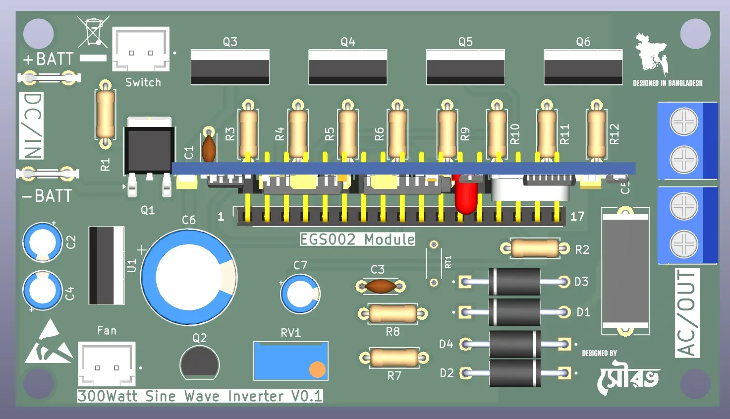
3D Autodesk CAD Model
An interactive 3D CAD visualization of the inverter enclosure assembly, showing the arrangement of heatsinks, transformer, choke, and the underlying PCB layout. You can orbit, zoom, and explode the model directly in the viewer:
Power Stage Architecture & SPWM Generation
The inverter utilizes a high-performance two-stage power conversion architecture:
• **DC-DC Booster Stage:** Elevates the low-voltage 12V DC battery supply up to a high-voltage 310V - 340V DC bus. This is accomplished using a high-frequency push-pull topology driven by an SG3525 switching controller operating at 50kHz.
• **DC-AC H-Bridge Inverter Stage:** Swings the high-voltage DC bus to synthesize 220V AC at 50Hz. An EG8010 ASIC controller generates high-frequency **Sinusoidal Pulse Width Modulation (SPWM)** signals, driving four power MOSFETs (IRF3205/IRF740) via IR2110 high-and-low-side gate driver ICs.
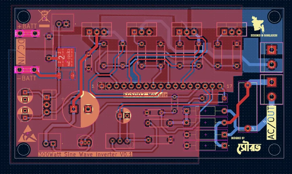
Power Stage PCB Layout
The PCB layout is optimized for thermal dissipation and minimal electromagnetic interference. High-current copper traces are reinforced with solder-filled copper wire to withstand currents up to 30A. A low-pass LC filter at the H-bridge output filters out the 20kHz switching carrier frequency, outputting a clean 50Hz sine wave.
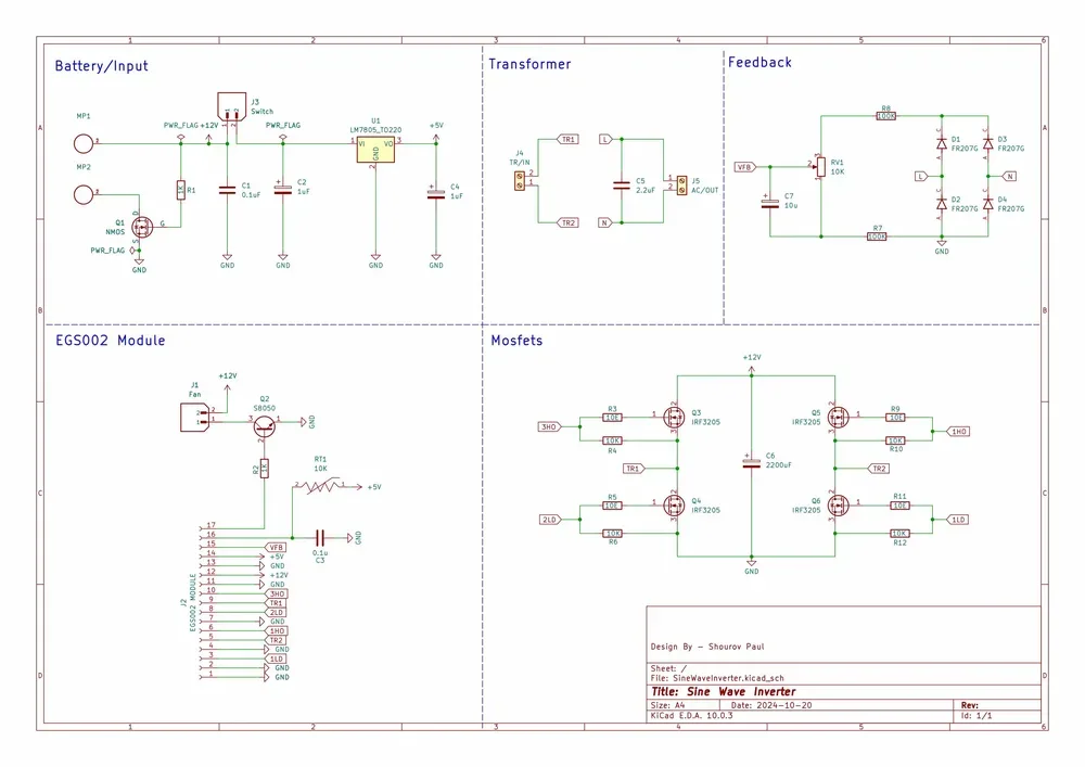
Schematic Design & Filter Topology
Firmware Core: SPWM Sinusoidal Lookup Table
EG8010_SPWM.ino
1// Sine wave lookup table values (1/2 cycle, 32 samples)
2const uint8_t spwmTable[] PROGMEM = {
3  0, 24, 49, 74, 97, 120, 141, 161,
4  180, 197, 212, 224, 235, 242, 247, 250,
5  250, 247, 242, 235, 224, 212, 197, 180,
6  161, 141, 120, 97, 74, 49, 24, 0
7};
8
9// Interrupt service routine for high-frequency SPWM switching
10ISR(TIMER1_COMPA_vect) {
11  static uint8_t index = 0;
12  static boolean halfCycle = false;
13
14  if (halfCycle) {
15    OCR1A = spwmTable[index]; // Set positive half-cycle pulse width
16    OCR1B = 0;
17  } else {
18    OCR1A = 0;
19    OCR1B = spwmTable[index]; // Set negative half-cycle pulse width
20  }
21
22  index++;
23  if (index >= 32) {
24    index = 0;
25    halfCycle = !halfCycle; // Toggle polarity
26  }
27}